Highstar Launches the HSD-2300kWh(L): A 1.25 MW / 2.3 MWh Liquid-Cooled Sodium-Ion Container System
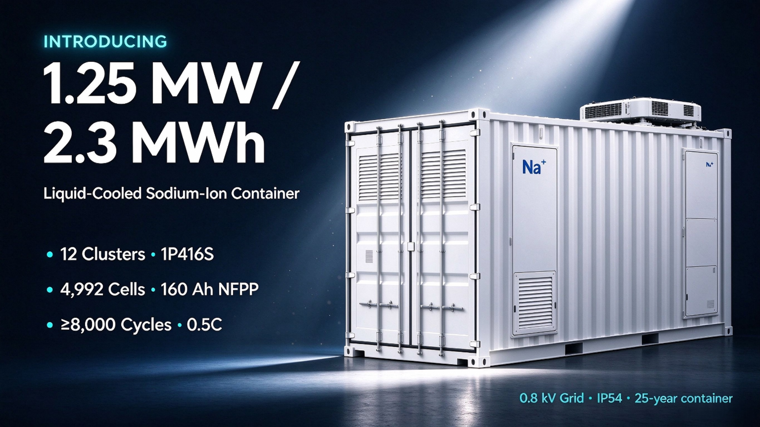
October 2026 — Jiangsu, China — Highstar Sodium has launched the HSD-2300kWh(L), a next-generation liquid-cooled sodium-ion storage system for utility-adjacent and large commercial-industrial projects. The release pairs a 2.3 MWh liquid-cooled battery container — twelve 1P416S clusters, a 40 kW dual-inverter liquid-cooling unit, quad-stage fire protection, and a combined busbar/switchgear cabinet in one standard shell — with a companion power-conversion and step-up skid. It is the direct power-class extension of the company’s 0.5 MW / 1 MWh system, built on the same NFPP chemistry with 2.88 V / 160 Ah cells rated 460 Wh — the cell platform behind the world’s first TÜV SÜD certified sodium-ion battery.
The container measures 6,058 × 2,550 × 2,896 mm with a DC window of 707.2–1,435.2 V, and the AC delivery is rated ≥1,250 kW at 0.8 kV / 50 Hz. The design is governed by the GB 51048 electric-ESS station code and references UL 9540 for storage-system safety.
From 0.5 MW / 1 MWh to 1.25 MW / 2.3 MWh: an extension, not a redesign
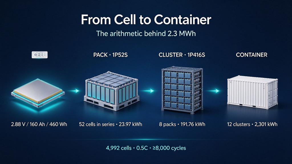
The 1 MWh release established the cell-to-container architecture and the delivery discipline; this system scales the same hierarchy, and every delta traces back to a documented choice:
| Level | 0.5 MW / 1 MWh (earlier) | 1.25 MW / 2.3 MWh (this launch) |
|---|---|---|
| Cell | 160 Ah NFPP prism (2.88 V, 460 Wh nominal) | Same cell |
| Pack | 1P52S (plus a 1P48S air-cooled variant) | 1P52S: 23.97 kWh @ 149.76 V nominal, IP65 |
| Cluster | 8 packs, series only | 1P416S = 8 × 1P52S + 1 HV box + 8 MSDs |
| Clusters | 6 | 12 |
| Cell count | 2,496 | 4,992 (12 × 8 × 52, counted by the BMS) |
| DC voltage | 624.5–1,435.2 V | 707.2–1,435.2 V (charge cutoff 1,435.2 V / discharge cutoff 665.6 V) |
| Rated energy | 1,142 kWh (1 MWh discharged) | 2,301.1 kWh |
| Conversion | 6 × 130 kW string PCS | 1 × 1,450 kW centralized, sodium-specific PCS |
| Thermal | 20 kW liquid-cooling unit | 40 kW Envicool dual-inverter, dual-loop unit + 1.5 kW dehumidifier |
| Step-up | 35 kV switchgear grid | 0.4/0.8 kV dry transformer (SCB13-1250), 0.8 kV bus |
The conversion topology changes from six strings to one 1,450 kW centralized PCS (max DC 1,595 kW / 2,500 A, max efficiency 99%, full load across 660–1,500 V DC, 1C/2C/3C-capable, -40 to 60 °C operation, altitude <5,000 m). The string-versus-centralized trade is addressed in the electrical section below.
How the system is assembled: arithmetic you can audit
Cell → pack. Fifty-two cells in pure series (1P52S): 52 × 2.88 V = 149.76 V nominal; × 160 Ah = 23.97 kWh (operating window 83.2–179.4 V). The cold plate is integrated in the module; cells are never paralleled inside the pack, so circulating currents are eliminated by topology.
Pack → cluster. Eight series packs + one high-voltage box + eight manual service disconnects = a 1P416S cluster, 1,198 V / 191.76 kWh. The HV box carries contactors, breakers, fuses and Hall sensors under BMS control.
Cluster → container. Twelve clusters in parallel + the combined busbar/switchgear cabinet = 12 × 191.76 = 2,301.1 kWh. Three-tier BMS (BAMS / BCU / BMU) supervises all 4,992 cells.
Container → AC. The companion skid integrates the centralized PCS, the SCB13-1250 dry transformer, and a load-break ring-main unit (vacuum switch, fuses, earthing switch, arresters, live indicators), delivering ≥1,250 kW at 0.8 kV.
Electrical design: four choices worth examining
1. A centralized PCS, not strings. One 1,450 kW converter means fewer power stages and simpler inter-container wiring — at the cost of a single power path for the whole site. Circulation risk is bounded by per-cluster MSDs and busbar fusing, but availability must be argued honestly: a PCS fault takes the full 1.25 MW offline. The 0.5 MW system keeps six independent strings; both topologies now coexist in one catalog, which is itself an honest answer to different availability preferences.
2. A wide DC window on a high-voltage platform. The PCS loads fully across 660–1,500 V while the system sits at 707.2–1,435.2 V; a 1,198 V nominal DC bus keeps the 1.25 MW class within 2,500 A devices, shrinking busbar copper and cable cross-sections.
3. Liquid cooling that reaches the pack. The 40 kW Envicool dual-inverter, dual-loop unit plus a 1.5 kW dehumidifier hold cell-to-cell difference within ≤3 °C inside a pack — the consistency argument behind the documented ≥15 % system-life uplift claim (manufacturer statement; test basis available on request).
4. Step-up lands on 0.8 kV. The SCB13-1250 (Dyn11) lifts the PCS 400 V output to the 0.8 kV point of common coupling, with temperature tri-cycle monitoring, over-temperature alarm/trip dry contacts wired to the emergency-stop chain, and RS485 telemetry; the ring-main unit provides local/remote switching with fuse protection.
Safety: quad-stage fire protection, from pack to water
The launch keeps Highstar’s four-stage fire concept, reviewed at design stage by State Grid disaster-prevention specialists:
- Pack level — every pack carries a non-pressurized perfluorohexanone (FK-5-1-12) automatic suppression loop: primarily chemical with physical action, colorless, low-toxic, non-conductive, no residue on protected equipment, extinguishing concentration ≤10 %, capable of repeated discharge with 24-hour re-ignition resistance;
- Cluster level — detection and targeted suppression per 1P416S rack;
- Electrical-cabin passive gas suppression;
- Water sprinkler plus a sealed, quick-connect external fire-water interface on the battery container.
The interlock chain: smoke/temperature/combustible-gas detectors crossing alarm thresholds trigger audiovisual alarms, command emergency stop from PCS and BMS, isolate the battery from the grid, discharge after a configured delay, then run post-suppression ventilation. The fire system carries its own emergency power supply — it arms even on full external blackout.
Beyond suppression: IP54 cabinetry, 50 mm class-A rockwool sandwich walls (≥1.5 h fire endurance), all-noncombustible enclosure materials, seismic design to intensity 9, C3 corrosion class, a 25-year container structure, early-warning gas detection, access control, water-drive and video monitoring.
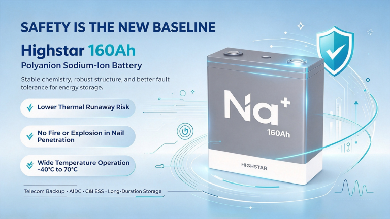
Sodium’s chemistry layer stays first in the defense chain — high thermal-runaway onset (>300 °C), nail-penetration tests passed without fire or explosion. The fire system’s job remains the same honest one: containment at the smallest possible scale.
Performance at a glance (battery container)
| Parameter | Value | Condition / source |
|---|---|---|
| Cell | 2.88 V / 160 Ah / 460 Wh | NFPP prism, TÜV SÜD-certified chemistry |
| Pack | 1P52S / 149.76 V / 23.97 kWh / IP65 | 318 kg; 1,096 × 804 × 247.5 mm |
| Cluster | 1P416S / 1,198 V / 191.76 kWh | rated 80 A charge/discharge (0.5C) |
| Container | 2,301.1 kWh / ≤43 t / IP54 | 6,058 × 2,550 × 2,896 mm; noise 75 dB @ 1 m |
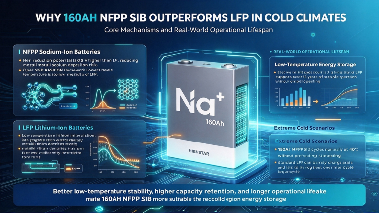
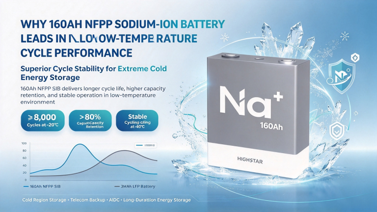
| Cycle life | ≥8,000 cycles at ≥70 % retention | 0.5C one-charge-one-discharge, 25 ± 3 °C standard protocol |
| Cluster energy efficiency | ≥98 % | 0.5C CC/CV to 3.45 V, 0.05C cutoff, standard test |
| Temperature | charge 0–55 °C; discharge -20–60 °C; storage -20–40 °C | system-level windows |
| Altitude / humidity | <5,000 m (derate above 3,000 m) / 65 ± 20 % RH |
0.5C is the long-duration signature. Eight thousand cycles at half-rate equals roughly two full cycles daily for eleven years, or one daily for over two decades — before the thermal-consistency uplift. Where a project needs 1C+ response (frequency regulation, UPS-grade power quality), the 0.5 MW string-PCS system and the UPS cabinet remain the designated products.
Two delivery models: AC-complete container, or DC-only
The same container ships in two contractual forms:
- AC-complete (this release): battery container + PCS/transformer/ring-main skid + EMS, ready at the 0.8 kV bus;
- DC-only battery side for buyers who hold their own PCS, transformer and grid-connection scope. A recent overseas due-diligence round confirmed the DC-side answers: ~2.28–2.3 MWh DC container, 0.5C maximum rate, 95 % system efficiency at 0.5P/25 °C, smoke + temperature + H₂ detection, single-point alarm / double-point aerosol release logic, high-concentration hydrogen exhaust interlock, auxiliary supply 100 A 3P+N+E at 380–415 V AC, and lifting/assembly/foundation drawings in the technical pack.
Note the efficiency split — 98 % is the cluster-level test value; 95 % is the DC-system delivery figure — both real, both conditional. Quote each with its basis.
The EMS covers monitoring (power curves, energy statistics, one-line view), dispatch control, predictive maintenance (alarm grading, work orders, spares, knowledge base) and safety interlocks; deployment follows the power-monitoring-network doctrine of security zones, dedicated networks, horizontal isolation and vertical authentication.
Applications — and the honest fit checks
- Renewables co-location / mandated storage: 1.25 MW / 2.3 MWh sits squarely inside typical wind/solar pairing ratios; the prefab container ships on flatbeds, and the design program claims ~40 % shorter site installation and 20–30 %+ land savings versus conventional air-cooled layouts (vendor figures; site-dependent).
- Large C&I campuses and microgrids: 25-year container with C3 coating for outdoor duty; coordinates with PV, diesel or grid per EMS strategy.
- Standalone/共享 stations: multi-container parallel expansion through the busbar cabinet.
- High-altitude and temperature-swung sites: -20 to 60 °C discharge, PCS starting at -40 °C, altitude to 5,000 m.
Before specifying, confirm three fit items: ① duty is 0.5C — rate-critical services belong to other products in the matrix; ② the charging floor is 0 °C — cold-morning charge windows in severe winters need an EMS strategy and pre-heat plan, this system does not claim sub-zero charging (unlike the 50Ah cell’s documented project configuration — don’t cross-quote); ③ centralized PCS availability math should be weighed against the string-based 0.5 MW sibling for your redundancy target.
Ordering and delivery
Standard scope: 12-cluster liquid-cooled battery container + 1,450 kW centralized PCS skid (0.8 kV) + EMS. Configurables: AC-complete vs DC-only boundary, ring-main options, high-voltage side class, corrosion class, EMS module set and dispatch protocols. FAT reports, lifting/foundation drawing packs and a fire-interlock demonstration ship with the contract; cycle and efficiency guarantees carry their stated test conditions in the quality agreement.
Where it sits in the matrix
The HSD-2300kWh(L) adds the long-duration energy-class container to the family: 50Ah high-rate cell → 8kWh home battery → C&I stack systems → 0.5 MW / 1 MWh container → this system. For standby power see the 41.2kWh UPS cabinet; for the full map read the complete selection guide.
Frequently Asked Questions
How large is the system?
1,250 kW AC at 0.8 kV with a 2,301.1 kWh battery container: twelve 1P416S liquid-cooled clusters, 4,992 cells of 2.88 V / 160 Ah / 460 Wh each.
What cycle life does it claim?
≥8,000 cycles at ≥70 % capacity retention under the 0.5C one-charge-one-discharge protocol at 25 ± 3 °C, with cluster energy efficiency ≥98 % under the same standard test.
How does it behave in cold weather?
The container discharges from -20 °C to 60 °C and charges from 0 °C to 55 °C; the PCS itself starts at -40 °C. Sub-zero charge acceptance is not part of the standard claim — specify an EMS pre-heat strategy for severe-winter sites.
What fire protection is built in?
Four stages: pack-level non-pressurized perfluorohexanone (repeated discharge, 24-hour anti-re-ignition), cluster-level detection and suppression, electrical-cabin passive gas suppression, and a water-sprinkler stage with a sealed external fire-water interface. The system carries its own emergency power and interlocks PCS/BMS shutdown automatically.
Can we buy the DC side only?
Yes. The DC-only delivery includes the detection/suppression set and auxiliary power at the documented configuration; the AC side — PCS, transformer, grid code — stays with your qualified integrator.
How does it differ from the 0.5 MW / 1 MWh system?
Same cell, same 1P52S → 1P416S hierarchy. This launch doubles clusters (6 → 12), switches from six 130 kW string PCS to one 1,450 kW centralized unit, moves the step-up platform to 0.8 kV, and doubles the liquid-cooling capacity to 40 kW.
References
- Highstar Sodium, 1.25 MW / 2.3 MWh Liquid-Cooled Energy Storage System Technical Proposal (2.88 V / 160 Ah configuration), internal engineering document, June 2025 / 2026 revision.
- Highstar Sodium, Container DC-Side Clarification Sheet (buyer due-diligence responses), October 2026.
- Highstar Sodium, 0.5 MW / 1 MWh Sodium-Ion BESS Technical Proposal (predecessor platform documentation).
- GB 51048 — Design Code for Electrochemical Energy Storage Station.
- UL 9540 — Energy Storage Systems and Equipment Safety Standard (design reference).
- Envicool — liquid-cooling unit product documentation (40 kW dual-inverter, dual-loop).
*Company contact: via the official contact page — www.highstar-sodium.com/contact/