Introducing the 0.5 MW / 1 MWh Liquid-Cooled Sodium-Ion Battery Energy Storage System
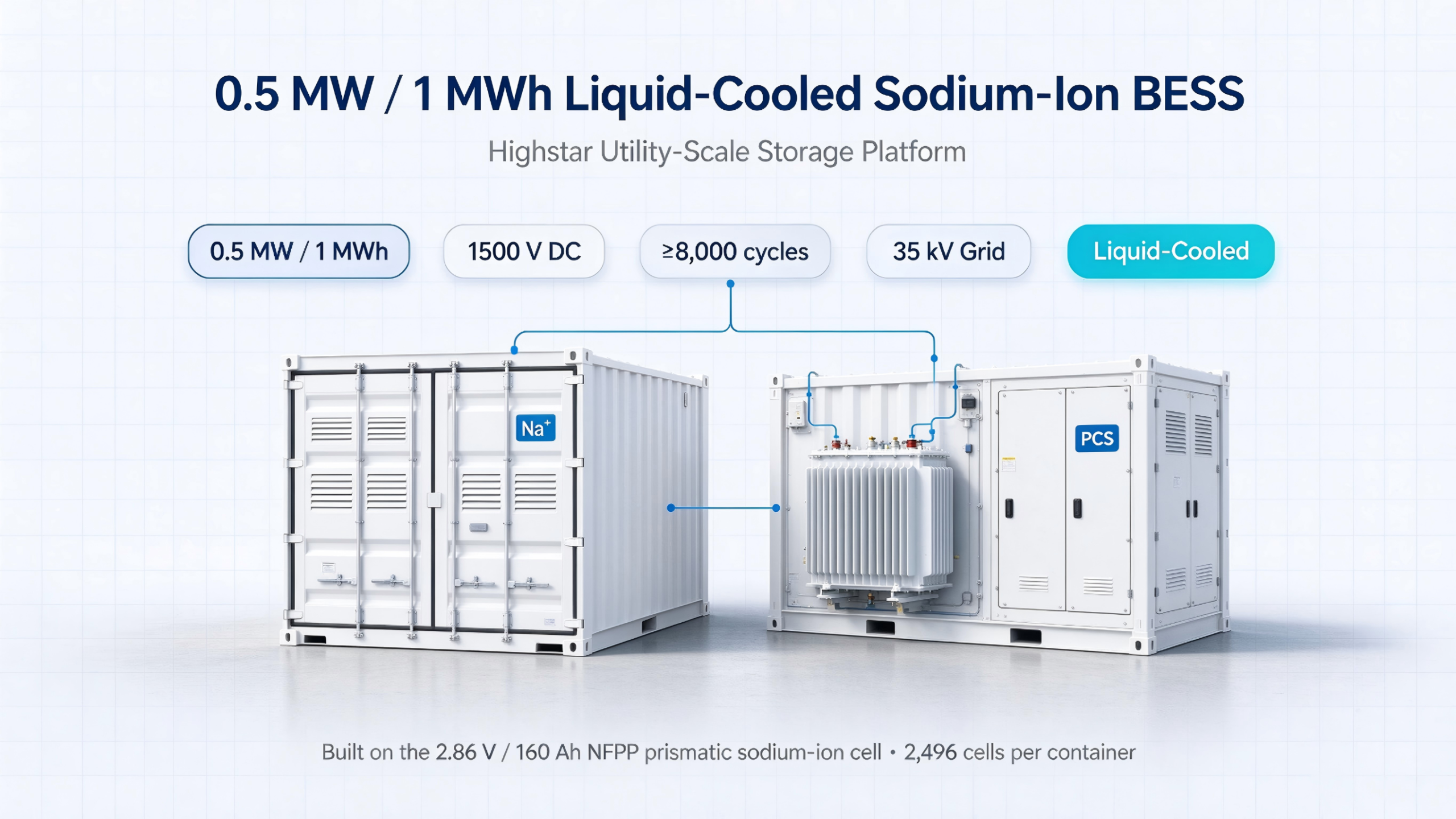
Product launch — October 2026.** Highstar Sodium today announced its first utility-scale sodium-ion platform: a 0.5 MW / 1 MWh liquid-cooled battery energy storage system pairing a 1.0 MWh liquid-cooled battery container with a 500 kW string-PCS step-up integrated cabin. The system is built entirely on the company’s mass-produced 2.86 V / 160 Ah NFPP prismatic sodium-ion cell and targets the grid side of the market — renewable integration, peak shaving, frequency regulation and microgrid backbone duty.
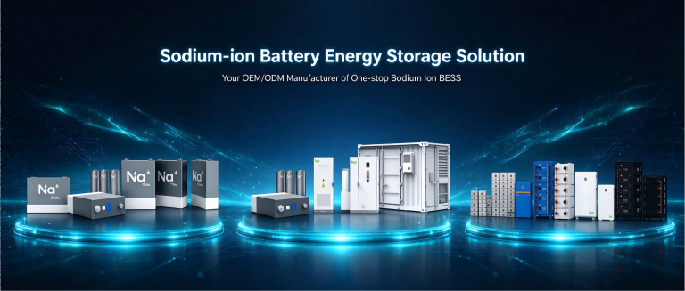
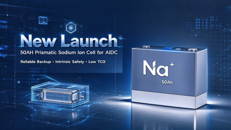
This launch completes the product ladder described in our 2026 sodium-ion storage selection guide: from the 15 Ah and 50 Ah cells, through 48 V home and telecom batteries, stacked commercial clusters and outdoor cabinets, to a full container system at megawatt scale.
Why this launch matters for sodium-ion storage
Sodium-ion battery technology has spent years in demonstration projects. The open question for grid buyers has never been whether the chemistry works — it is whether a sodium-ion system can meet utility specifications at real scale: 1,000 V-plus DC architecture, liquid thermal management, string conversion, certified fire protection and single-crane deployment.
The 0.5 MW / 1 MWh system answers at the platform level:
- Two-hour duration (1 MWh / 0.5 MW) — the standard window for daily renewable shifting and peak management in most grid-code markets.
- 1500 V-class DC architecture with a battery container operating from 624 V to 1,435.2 V, aligned with modern string-PCS input ranges (630–1,550 V).
- A sodium-ion battery core, not a repurposed lithium enclosure — every major subsystem (cell, pack, cluster, BMS tiers, fire logic, coolant loop) is specified around NFPP sodium-ion behaviour.
Marketing quote placeholder — suggested line for the launch press release: “This system takes sodium-ion from demonstration parcels to the standard utility building block. One container, one cabin, 35 kV to the grid.” Replace with your official spokesperson quote before publication.
System at a glance
| Parameter | Specification |
|---|---|
| Rated power / energy | 0.5 MW / 1 MWh (2-hour system) |
| Architecture | 1.0 MWh liquid-cooled battery container + 500 kW PCS step-up integrated cabin |
| Cell | 2.86 V / 160 Ah NFPP prismatic sodium-ion (~0.46 kWh each) |
| Battery string | 1P52S module → 8 modules in series per cluster (1P416S) → 6 clusters per container |
| Total cells | 2,496 (48 packs × 52 cells) |
| Configured energy | 1.142 MWh (container), nominal discharge 1 MWh |
| Cluster nominal voltage | 1,189.76 V; operating range 624.0–1,435.2 V |
| Continuous rate | 0.5 C charge / 0.5 C discharge (80 A) |
| Cluster cycle guarantee | ≥8,000 cycles at 0.5 C with ≥70% capacity retention (25 °C ± 3 °C test basis) |
| PCS topology | 6 × 130 kW string modules, three-level, max conversion efficiency 99% (module peak, per datasheet) |
| Grid interface | AC 400 V via SCB11-550 kVA dry-type transformer to 35 kV, 50 Hz |
| Thermal management | 20 kW liquid-cooling unit + 1.5 kW dehumidifying air conditioner; pack cell-to-cell ΔT ≤ 3 °C |
| Fire protection | Quadruple architecture: pack-level detection and perfluorohexanone (FK-5-1-12) suppression, passive gas suppression in the electrical cabin, water-sprinkler system; 24-hour anti-reignition design |
| BMS | Three-tier BMU / BCMS / BAMS; SOC accuracy 3%, SOH accuracy 5% |
| Enclosure | Non-standard 10-ft walk-out-free container, IP54 (packs IP65; PCS module IP66 / rack IP54) |
| Operating window | Charge 0 °C to 55 °C; discharge -20 °C to 60 °C; storage -20 °C to 40 °C |
| Footprint / weight | ≤ 5,000 × 2,700 × 2,896 mm; battery container ≤ 30 t (estimate) |
| Structure design life | Container frame designed for 25 years; corrosion class C3 |
| Altitude / noise | ≤ 3,000 m (derating above); ≤ 75 dB(A) at 1 m from container |
| Communications | CAN, RS485, TCP/IP; Modbus TCP/RTU, IEC 104, IEC 61850 |
Inside the battery container
The DC side is a 6-cluster liquid-cooled design. Each 1P416S cluster strings eight 1P52S packs — modules are series-only with no internal parallel groups, which keeps cell currents identical across each string and removes one classic failure path (inter-string circulating current).
Each pack integrates its own BMU, MSD disconnect, and a dedicated inlet/outlet to the container coolant loop. Cold-plate simulation shaped the flow channels for lower pressure drop and higher heat-carrying capacity; each box carries 38 NTC sampling points distributed along the module axis, so the BMS sees the true hot and cold cells, not an average.
What ΔT ≤ 3 °C buys you. Cell-to-cell temperature spread is the hidden driver of aging mismatch in containerised storage. The design target of ≤ 3 °C inside each pack, versus typical wind-cooled spreads, is specified to extend battery life by at least 15% — and it is the reason the cluster is guaranteed at ≥ 8,000 full cycles to 70% state of health.
The cluster high-voltage box integrates contactors, breakers, protection fuses and Hall sensors; all positive and negative terminals are front-outlet wired, so field maintenance never works behind a live enclosure.
String PCS: six independent paths instead of one parallel bus
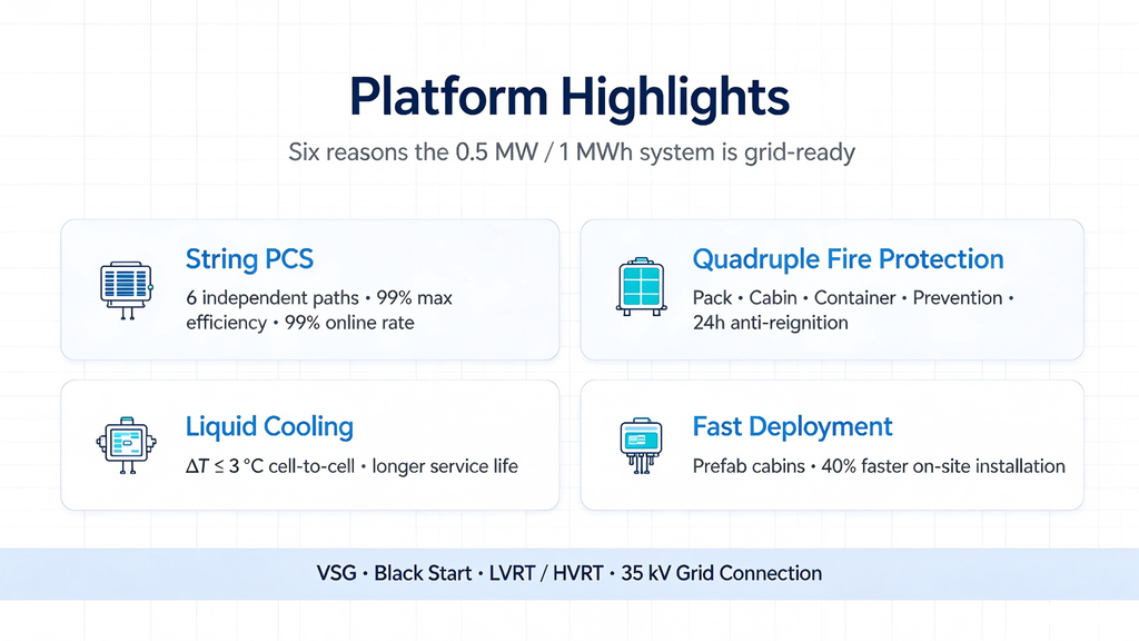
The 500 kW step-up cabin carries six 130 kW string converters, one per battery cluster. This is the same architecture that utility lithium fleets adopted, and it fixes a specific weakness of paralleled designs: when clusters share a DC bus, voltage differences push circulating currents between batteries, and one failing cluster can drag the whole unit offline.
With per-cluster strings:
- Each converter runs independently — the system keeps operating at reduced power when one path is down, with an online rate specified at 99%.
- Cluster-level MPPT-equivalent control means each battery string charges and discharges on its own window, which protects sodium cells from forced-current stress during imbalance events.
- DC input spans 630–1,550 V with per-branch current to 230 A, comfortably covering the full 624–1,435.2 V battery window.
Downstream, a 550 kVA dry-type transformer (Dy11, 1.1× continuous overload) steps 400 V to 35 kV; the high-voltage compartment carries load switch or vacuum breaker, disconnectors and arresters; the low-voltage compartment ships with integrated transformer protection, metering and communications plus a 1 kVA UPS with 30-minute backup.
Safety architecture: four layers, tested logic
Sodium-ion chemistry starts with a materially lower thermal-runaway propensity than lithium systems — but a grid-scale product has to defend safety at the system level regardless of chemistry. This platform stacks four independent layers:
- Pack level — gas detection and perfluorohexanone (FK-5-1-12) nozzles inside every pack; suppression agent acts at the earliest observable stage.
- Cluster/electrical cabin — passive gas suppression covering HV boxes and cable compartments.
- Container — water-sprinkler backup sized for sustained cooling after agent depletion.
- Prevention — the liquid loop itself: forced heat removal and inter-module heat redistribution suppress the conditions under which runaway propagates.
The design requirement is multiple discharge capability with 24-hour anti-reignition. Automatic fire alarm, combustible-gas detection and emergency ventilation are interlocked with BMS contactor opening; the design references GB 50116, GB 50370 and UL 9540 as standard baselines (design reference standards — confirm your certification scope separately before citing them in tenders).
Grid behaviour: what the PCS actually does at night
Beyond basic PQ operation, the cabin supports:
- VSG (virtual synchronous generator), PQ and VF modes, off-grid parallel operation and black start — the system can anchor a microgrid or restore a site after a outage.
- LVRT and HVRT ride-through per GB/T 34120 requirements (current 2023 edition), with ride-through priority logic before protective tripping.
- Four-quadrant independent active and reactive control, power factor across -1 to +1.
- AGC secondary frequency response, primary frequency response, AVC-coordinated voltage support and peak-shaving/valley-filling dispatch through the EMS layer.
- Source-grid-load precision switching, so the unit participates in coordinated curtailment-recovery programmes — recovering energy that would otherwise be dumped.
Islanding detection trips the grid interface within 200 ms; frequency protections act in 0.2 s; DC overvoltage breaks out in 1 ms. Full protection matrix (14 defined events with setpoints and trip times) is documented in the technical proposal.
Deployment: two lifts, then wiring
Both units ship as pre-engineered cabins — battery container and step-up cabin — flatbed-transportable with internal racking frozen at factory. Compared with conventional building-based substations, the prefab approach shortens on-site installation time by 40%: foundation, two crane placements, medium- and low-voltage terminations, commissioning. For distributed generation grids and rooftop-or-field retrofit projects, the schedule reduction is often the difference between hitting and missing a connection deadline.
Where this product fits in the sodium-ion range
| If you need… | Look at |
|---|---|
| Utility / new-energy co-location, 35 kV connection | This 0.5 MW / 1 MWh container |
| Distributed wind smoothing with outdoor placement | Cabinet sodium-ion BESS for wind farms |
| Commercial parks, stacked capacity, 400 V side | High-voltage stacked commercial BESS |
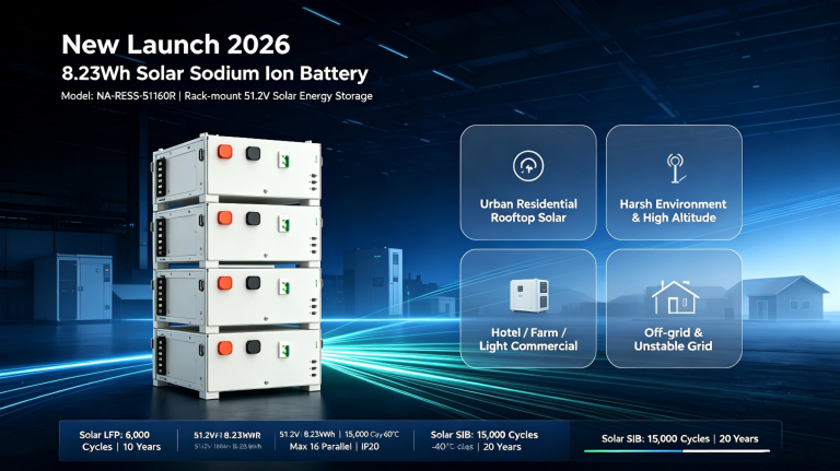
| 8 kWh home solar battery | 8 kWh solar sodium-ion battery |
| Cells and packs for your own integration | 50 Ah prismatic sodium-ion cell and the full range guide |
| EU compliance questions | Sustainability and the EU Battery Regulation |
FAQ
Is this a 1 MWh or a 1.142 MWh battery?
The container configures 1.142 MWh of cell energy; the rated discharge envelope sold in the product name is 1 MWh. Headroom covers degradation, balancing windows and temperature derating so the delivered rating holds through the guarantee period.
Why is the discharge floor -20 °C when sodium cells are tested colder?
The cell chemistry supports colder service, but the system window is set by the lowest-rated component in the loop — coolant properties, seals, sensors and PCS ambient limits. A liquid-cooled container pre-conditions its own battery cabin, so -20 °C ambient still starts inside a thermally managed box rather than on an exposed rack.
Can the system work off-grid?
Yes. The string PCS supports VF and VSG modes, off-grid parallel operation and black start, so the unit can form a grid for a microgrid or essential-load island, then return to grid-tied PQ mode when service is restored.
What warranty and cycle basis apply?
The technical proposal guarantees ≥ 8,000 cycles at 0.5 C with ≥ 70% capacity retention at 25 °C ± 3 °C test conditions. Contractual warranty terms are project-specific; request the current annex from the sales team.
Is sodium-ion ready for 35 kV utility tenders today?
The standards scaffolding exists — the design references GB 51048, GB/T 36547, GB/T 34120 and NB/T monitoring specs. Utility acceptance depends on your market’s grid code and the project’s witness testing; Highstar supplies single-line diagrams, protection setpoint tables and type-test documentation packs per project.
What does the 99% efficiency figure refer to?
It is the PCS module’s maximum conversion efficiency from the datasheet, measured at the converter terminals. Do not read it as AC-to-DC round-trip efficiency — a full-chain figure must add transformer losses, auxiliary loads (liquid cooling, dehumidifier, UPS) and dispatch cycles.
References
- Highstar Sodium, 0.5 MW / 1 MWh Sodium-Ion Energy Storage System Technical Proposal, December 2025 (source document for all specifications in this article).
- GB/T 34120 — Technical requirements for PCS in electrochemical energy storage systems (2023 edition).
- GB 51048 — Design code for electrochemical energy storage stations.
- GB/T 36547 — Technical regulations for connecting electrochemical energy storage systems to the power grid.
- UL 9540 — Energy storage systems and equipment safety standard (design reference).
- National Development and Reform Commission, Basic Rules for Medium- and Long-Term Electricity Markets, effective 1 March 2026.